In previous blog posts, I have covered how to develop testing infrastructure for Hardware in the Loop systems (HIL). With this video, I cover reasons why people decide to use an HIL system.
Note: One of the reasons is never “Because it is there.”

In previous blog posts, I have covered how to develop testing infrastructure for Hardware in the Loop systems (HIL). With this video, I cover reasons why people decide to use an HIL system.
Note: One of the reasons is never “Because it is there.”

With this post, I will share some of the methods I have used over the years to make my Simulink models more readable.
Resizing subsystems is a common suggestion to making diagrams more readable. A step beyond that is to reorder the ports so that the connections between multiple subsystems are more readable.


With this Before/After example, I have done three things
When I am entering in an equation into Simulink, I ask myself 2 questions


In text form, the Pythagorean theorem is quickly recognized and understood. When written out as a Simulink equation it takes slightly longer to understand.
Note: I do have a caveat, if the mathematical operations are series of gains, for instance when converting from one unit to another, then keeping the calculations in Simulink is fine.
Merging data from conditionally executed subsystems requires the use of the Merge block. When the subsystems have multiple output ports routing the data quickly becomes cumbersome. This can be addressed by creating a virtual bus to pack and then unpack the signals.

Note: Using a virtual bus will allow Simulink/Embedded Coder to optimize the memory placement of the signals. If a structure is desired, then a bus object should be defined and used.
When I create a Simulink subsystem, I aim to have a limited number of active blocks in the subsystem (40). A limited number of used inputs (5) and a limited number of calculated outputs (2).
Notes: Subsystems that are integration subsystems (see this Model Architecture post) can and should break this rule.)
As a general rule of thumb, I recommend that models have a “depth” of 3. Navigation up and down the hierarchy quickly can lose a reviewer. Likewise, for given model, I recommend between 30 and 60 subsystems in total.

This recommendation holds for a single model. For integration models, each “child” model should be treated as a single unit.
These are just a few of the recommendations that I have hit upon in the past 18 years. I would be curious to hear your thoughts and recommendations.

Interfaces between low-level device drivers and algorithmic software have multiple unique issues. These issues exist in traditional text-based development processes and in MBD workflows. Let’s review the challenges and methods for meeting the challenges.
 I decompose the hardware challenges into two categories; conceptual and technical.
For software engineers, the concepts behind hardware interfaces are frequently a source of error.
The technical challenges are standard component-to-component interface issues.
Understanding the hardware challenges we can now address them. The conceptual challenges are addressed through education.

Technical challenges are handled with education and patterns.

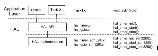

Well defined interfaces between hardware and software is provide clarity in communicating design intent. The model architecture can be developed from the basic architecture proposed here, with the hardware inputs and outputs being a top level integration system.


Interacting customers are the way I learn; each time I go on the road I have the chance to interact with my customer; see the challenges they face and the ways in which they attempt to solve them. So with reflection, what are the top 3 things I learn from customers.
Model-Based Design processes involve many design patterns (small work objects) and workflows (multiple patterns executed in a logical sequence). Customer patterns and workflows, both the good and bad, evolved over time in response to challenges they faced. Often the work that I am brought in to do is to help my customers both simplify and improve their existing workflows.
Often the work that I am brought in to do is to help my customers analyze then simplify and their existing patterns and workflows. This analysis both allows me to learn from the customer as well as share the lessons I have learned over time from other customers.

The development process is only as strong as the team working on the project. Ideal teams have a coordinated objective and a unified understanding of how the Model-Based Design process should proceed. Communication of both the lessons learned and the obstacles encountered makes is a major key to succeeding.
At the start of an MBD adoption process deadlines are set, often, with a limited understanding of the full set of tasks involved in migration.  They are estimates. The way customers evaluate and update deadlines should be based on the following rationale.
One of the great joys of being a consultant is having the chance to work with a wide range of individuals, each of whom brings a unique insight into the software development process. I look forward to my next 20 years of interactions.

With this video, I summarize the approach I take to selecting the type of projects I work on. I call it the 20-60-20 rule and it represents the balance I strike between learning new material, deepening my understanding of the material and teaching others.

These blog posts have focused on the adoption of Model-Based Design. The choice of the word “adoption” was intentional. When I visit a customer I tell them the following.
“80% of what I will recommend is generic best practices, common
across all Model-Based Design. The next 10% is a selection of common
patterns in use relevant to your industry and regulatory needs.
The last 10% is the unique part of your development; your intellectual property”
Why do I say this? Model-Based Design, from an architecture, data, and V&V perspective is now a mature field. In a mature field, time should be spent on developing the IP aspects of design, not infrastructural components. To that end, there is a significant body of best practices available for companies to reference. (See the reference page for a small subset.)
As this blog has spoken about on a number of occasions adoption is a process. To succeed there are 5 key activities that need to be performed

Success often comes from knowing when to ask for outside help, either from other groups within your company who have already blazed a trail or from outside support groups (such as training and consulting.) Utilizing support early in the adoption process enables a faster rate of adoption with fewer implementation issues.


Very few projects start off with a clean slate; the majority have some body of existing text-based code (C/C++/Asembler) which needs to be either translated or wrapped into the Model-Based Design environment. For the cases where translation is the desired path, the objective should be the translation of the essence (e.g. requirements) not the content.
First, every programing language has unique constructs which may or may not be directly replicable in other languages. Because of this, a common failure mode is to try and directly replicate coding patterns in the MBD environment.

Second, when you translate the based on the requirements you have the opportunity to improve upon the existing code.
It is common with text-based algorithms to implement basic functions such as table look ups, integrators, etcetera. While in some edge cases the text-based implementation is more efficient this is less common with the growing maturity of Model-Based Design tools.

Further, the small efficiency gains from the existing implementation are frequently less important than the clarity found by using built in blocks.
In text based languages truth tables and state machines are implemented as either a series of if/then/else or switch/case statements. Within MBD environment both truth tables and state machines have direct implementations.
The final note, there are some areas where text based modeling makes the most sense. Generally, this is in the area of long complex equations. While they can be rendered in block form they are more easily read in text form. With that in mind, I recommend using MATLAB blocks for longer equations.

The image above, the Pythagorean theorem, is relatively simple. Yet even it would be more easily read as
C = sqrt(A^2 + B^2)
When translation occurs it is important that the new implementation is validated against the behavior of the existing code. Failure to do so can result in larger system level errors.
In my translation example, I used the simple phrase “I have the cutest cat in the world” I submit the following images to back that claim up


In a recent customer conversation, I was asked if there was a mapping of Model-Based Design (MBD) constructs to the concepts of “smells” found in Martin Fowler Clean Code. Fowler’s book was written targeting the Java, however, many of the concepts have direct mapping onto other programming languages. Maping onto other object-oriented text-based languages are easily seen. Hence the question of how OO smells could be mapped onto MBD.
Note: I am reviewing this in the context of developing embedded code using Simulink and Embedded Coder. The Clean Code was written with object-oriented user interfacing code (e.g. web pages, spreadsheets,…)
Fowler’s book defines 7 primary sources of smells:

For some of the smells, there is a direct and easy mapping.
Comments: Models are, to an extent, self-documenting. Additional documentation should be added as needed. Fowler’s recommendation on keeping comments concise and up-to-date are directly mappable.
Environment: The smells in this section deal with automation of the build and test steps. There is a direct mapping for these smells and the recommendations for automation are standard for MBD environments
Naming conventions: For information on naming conventions (from and earlier MathWorks blog I wrote): A few thought on Naming Conventions
Tests: The smells for tests are standard recommendations for testing. Earlier blog posts on testing can provide the mapping onto these smells.

Of the 7 smells, I want to spend more time looking at both the “Functions” and “General” groupings.

Fowler has 4 smells related to functions, of the 4 MBD conforms to 1.5 of them.

The general category includes 36 different code smells; I have subcategorized them into N themes
The concepts put forth in the book “Clean Code” represent a useful set of guidelines for understanding coding best practices. To the extent that models map onto code the concepts behind “Clean Code” apply. However, MBD abstracts many concepts behind coding into a higher level language, placing the clarity and encapsulation of the actual code into the hands of the code generation tool.
Late in my conversation with the customer, I realized that I was talking to someone from Denmark about smells. I regret that I did not take the opportunity to make a reference to Hamlet. (Something is rotten in the state of Denmark)


.I drive a vehicle with an all drive-by wire setup. Drive-by wire brake, throttle, and PRNDL (the shifting mechanism for those of you not in the Auto Industry (Park, Reverse…) While as a controls engineer, and an environmentalist, I like both the performance increase and the weight savings to fuel savings that this brings it raises the question, what do you do when the system fails?

The first rule of safety critical software (and a break in a vehicle is safety critical) is to fail in a safe fashion. There are several modes in which a brake can fail, from worst to best
First, what is a partial failure? A partial failure is when part of, but not all of, a redundant system sends back data that is not in alignment with the other parts. Standard protocols for drive by wire brakes is to have 3 redundant sensors to determine
Of the four scenarios, the first is the most dangerous and poses an interesting question “what is the fail safe behavior?” Hard braking could result in a rear end collision. Failure to brake could result in running into someone. Of course, this problem is no different from the one found in traditional fully mechanical/hydraulic systems. For an overview of what to do if this happens, take a look at this article.
So what does it mean to “fail friendly?” In a fail friendly scenario, the objective is for the system to maintain the maximum functionality without putting the user or the device in danger. In the example of the brake failure, with an all electronic version, the vehicle could allow driving at speeds up to 5 mph. This mode allows the driver to safely move the vehicle off of roads into a safe parking location.
The way in which systems fail directly impact the end users experience of the product. Providing the secondary fail friendly mode results in a more positive user experience.

While traceability plays a key role in the software development process for many groups it presents as a high impact burden. Modern software tools can simplify the traceability process however it all begins with the requirements.
The objective of traceability is to ensure that requirements are met in the final product.  This is achieved by the creation of traceability “check-ins” at each stage of the development process. A check-in serves two purposes. First, they ensure that the design process does not “drift” too far from the requirements. Second, they provide formal documentation of adherence to the defined development processes.
Check-ins should be an automated processes where information is cross checked between the current state of the models and the requirements. If the requirements are written in a testable format than the check in consists of running the tests and a human verification of the test result. If they are not written in a testable format or the complexity is such that automated testing is not possible then a manual review is required.
The primary deliverable of the check-in is a traceability report. It documents that at each step in the process the model and related artifacts were validated against the requirements.

Traceability is one of the core activities of a safety critical software design process. Implementation of automated requirements tracing is greatly simplified in a Model-Based Design environment that includes simulation capabilities.