What is Model-Based Design?

For the past 5 months, I have worked on this blog without giving a definition of Model-Based Design and while the definitions of Model-Based Design vary there are a few common concepts.  (Note: for this blog post I will only be considering graphical modeling languages such as Simulink.  It is possible to follow a Model-Based Design approach using textutal languages however there are additional burdens in doing so)

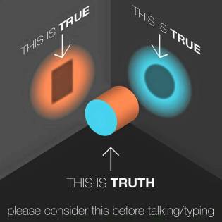
One truth – many uses

Core to all Model-Based Design workflows is the concept of a “model object” which is used in multiple phases of the design process.  That model object, or collection of objects, is elaborated during the design process, e.g. transforming an initial “shell” model into a fully elaborated model at the deployment phase.  Then using the deployment phase version of the model during the validation phases.  sdlc_vmodel

By maintaining a “one truth – many uses” model the number of handoff between people and roles is reduced thereby minimizing the introduction of errors.

telephone-game


Model represents reality

The model both represents and helps your understanding of the real world.  The representation is inherent, you design the model to encompass the physical and event driven phenomena of the system.

one truth, many persrpectives

The aspect of understanding comes in for complex systems where it is difficult, or even impossible to understand how the system will react to a given input.  (Note: “complex” is a relative term, even a “simple” dual pendulum is not easy to visualize.)

Abstraction

Finally, the goal of MBD is to abstract implementation from design details. Modeling languages represent aggregate concepts into representative blocks.  By removing the implementation details engineers can focus on functionality and safety while software architects can system level composition.

Example of abstract art
Mondrian “Composition No. 10

Final thoughts

This short introduction, by its very nature, cannot go into detail of how Model-Based Design is applied.  However, my hope is that by keeping the three key ideas of MBD, “one truth, many uses”, “model represents reality” and “abstraction” you will have a better understanding of Model-Based Design.


By request: M.A.A.B. style guidelines…

In the 6 months of writing this blog, I have received multiple requests for more information about the MAAB style guidelines.  The requests are for information on the rationale behind the rules and explanation of specific rules; I will address both in this post.

History of the M.A.A.B. style guidelines

The MathWorks Automotive Advisory Board (MAAB) was originally established to coordinate feature requests from several key customers in the automotive industry. The inaugural meeting in July 1998 involved Ford, Daimler-Benz, and Toyota.

inTheBegining

The MAAB is an independent board that develops guidelines for using MATLAB®, Simulink®, Stateflow® and Embedded Coder®.  MAAB meetings now involve many of the major automotive OEMs and suppliers, and focus on the usage and enhancements of MathWorks controls, simulation, and code generation products including Simulink, Stateflow, and Embedded Coder.

By the time of the version 3.0 release, the M.A.A.B. style guidelines were in use across multiple industries having outgrown their automotive origin to become the reference for aerospace, medical and industrial automation industries.

My involvement with the M.A.A.B. style guidelines

Back in 2005 when I joined The MathWorks my first task was to update the M.A.A.B. version 1.0 to version 2.0; the update was released in April of 2007.  architectWith a span of 9 years between the initial release and version 2.0, there were significant updates to both The MathWorks tools and the accepted user workflows.  With a few minor updates between version 2.0; version 3.0 was released in August of 2012.  Like the previous update, the version 2.0 to 3.0 enabled new workflows and addressed new tools and functions in the Simulink, Stateflow, and MATLAB models for MBD development workflows.

Across both releases, I helped guide the debate between those and wrote these guidelines.  Providing both the technical background from The MathWorks perspective and experience gain from working across multiple industries.

Understanding the guidelines

The M.A.A.B. guidelines working group had four primary objectives in mind when they were working.  With that in mind, guidelines should

  1. Improve model clarity
  2. Prevent unsafe modeling patterns
  3. Have minimal impact on the end user
  4. Be useable across companies

Model clarity

Model-Based Design was seen as a method for clearly communicating design intentions. Examples of these rules include

  • na_0004: Simulink model appearance
  • db_0043: Simulink font and font size
  • db_0042: Port block in Simulink models

By following common design patterns users can quickly and easily understand the models.

Prevention of unsafe modeling patterns

Within any modeling domain, it is possible to create design patterns that can result in unsafe behavior.  The two most common examples of this are divide by zero behaviors and “hard” floating point comparisons (e.g. FloatVar == 1)

220px-TI86_Calculator_DivByZero

Minimize impact on end users

The MAAB working group recognized that rules that place a high burden on engineers will be ignored or subverted.  In part to address this The MathWorks created the Model Advisor tool which automatically checks models for compliance with the MAAB style guidelines (other, custom, checks can be added)

Support use across multiple companies

The final point and one that often introduces confusion is the fact that the guidelines were written to support workflows for companies with different design patterns and workflows.  Because of this there are multiple checks that state “Please select either pattern A or pattern B”  (See NA_0005)


Final thoughts

The M.A.A.B. style guideline is intended to be a living document.  End users should take it and modify it to fit their specific needs.  By its nature, it is a conservative document; intended to meet the needs of multiple companies.  For more information on how to utilize modeling guidelines the following paper SAE paper or the summary technical article on The MathWorks site.


Know your history: The Stateflow block

The history junction block in Stateflow™ is a simple, powerful, and often misunderstood entity.  In this blog post, I will try to explain the use of the history junction, through a, hopefully, humorous example.

The Model

For this example, I have coded two versions of the same model, one with the history block and one without.  By doing so I can illustrate the effect of the block.

HistoryJunction

In this example, the first state is the “MortgageStatus”; it has three substates, start of loan, paying off loan and you own your home.  If all progresses normally you will be in the final state after 30 iterations of the chart.

However, there is a second top level state, “BankFraudOccured.”  For this model, I have this configured to be true every 10th cycle.  So let’s look at the results with and without the history junction.

The results

The function of the history junction is to allow users to return to the last active substate within a super state; without it, the user returns to the default substate.  If we look at the two graphs we will see the effect of history junction.

mortgageResults

In the left-hand graph, the instance with the History Junction, the effect of the “bank fraud event” does not impact the payoff of the mortgage.  However, in the right-hand graph, the bank fraud “resets” the mortgage to the “NEW” state and keeps the lender paying off indefinitely.   This can be clearly seen by looking at the Sequence Viewer.

sequenceMortgage.png

The red boxes her show where the model transitions to and from “BankFraud.”  With the history junction in place, you go right back to paying.  Without you follow the default junction to the starting substate.

Words of caution

So in this first example, we had a just a single state connected to our main state. Now let us take a look at a multi-state example

refi.png

In this example, the History Junction would resultmonopoly

in the state returning to “Paying Off” without going through the “Start of Loan” state.   The history junction applies to all transitions into and out of the parent state.   To correct for this the “Refinance State” needs to be to be “Start of Loan” state

refiRight.png

Final thoughts

The first iteration of MAAB style guidelines recommended against the use of the history junction.  With version 2.0 this recommendation was removed and it opened up new modeling patterns for our end users.  Use of the history junction enables multiple design patterns that are difficult to create without it.  Hopefully, this post sheds some light on its proper use.

Resources in support of adoption

One of the most common questions asked about adopting Model-Based Design is “What sort of resources do I need to succeed?”   Since it is a common question I have a ready answer, there are three things that you need.

  1. Support from management:  Managerial support for initial projects can be at the local level, however, for full adoption across a company VP level support is required.
  2. A correctly scoped project:  As written in early blogs identifying the correct initial project is critical for success.
  3. Engineering resources: The engineer resources represent who will be doing the work on the project.  This is the subject of the current blog.

Engineering resources

the-rule-of-three

In the initial stage, my recommendation is that you have at least 3 engineers with

  • 5+ years with the company
    (Preferably one with at least 10)
  • 80% of their time dedicated to the project
  • Exposure to multiple stages of the software development process

Why these recommendations?  First with respect to experience; there are two aspects here.  You need someone who understands the complexity of the existing project, past problems, and past successes so they can accurately judge the MBD processes.  Second, people with experience know who to talk to when there are issues that are outside of their scope.

Interacting-with-Teams1.jpg

The next aspect is the percentage of “on-project” allocation.  Adopting any new process requires dedicated time to study, learn, try, fail and adapt.  If resources are split between multiple projects the time required to digest the new information will be lost.

The reason for multi-stage exposure should be self-evident, the engineers need to understand how their suggested changes to the development process affect people across the organization, not just in their local domain.  At a minimum, these experienced engineers should know when to pull in outside resources for consultation.

Final thoughts: Why 3?

The rationale behind having a minimum team of three engineers is to provide diverse viewpoints on the decisions required as part of the adoption process.   Following these recommendations greatly increases the probability of initial projects succeeding.

34-1024-1024-l
Macbeth witches brew recipe

Education of an orginization…

Successful deployment of a Model-Based Design process is dependent on the education of the development group and then, in turn, the final engineers.  The training requirements for the deployment group and the engineers have some overlap, however, by their nature, the development group will have higher level requirements

Core and supporting areas for training

Adopting Model-Based Design requires learning new skills and adapting existing skills to a new environment.

landing-training-1150px-wide

There are 4 core areas for training an additional 3 supporting areas

Core

  1. Model and system architecture: The model and system architecture provides guidelines for model construction and system integration.
  2. Data management:  Data management enables data driven development workflows and allows for design of experiments within the MBD context
  3. Requirements workflow: Software development processes should begin with well-written requirements documents.  Model-Based Design simplifies the traceability of requirements from creation to final deployment.
  4. Verification and validation: The verification and validation processes are greatly accelerated in the Model-Based Design environment due to the simplification of early simulation of the software artifacts.

Supporting

  1. Version control processes: Use of version control software continues from the traditional software development processes.  The key lays with the artifacts under management.
  2. Documentation processes: Documentation covers both the creation of training material and the generation of tracking and V&V documentation.
  3. Bug tracking software: Like version control processes bug tracking software continues the use from traditional software development processes.

Methods of training

When adopting Model-Based Desing training consists of both formal training and informal training.  The first line of training is tool specific training, e.g. how to use individual tools.  This provides the grounding on their use.

Once a baseline understanding of the tools has been acquired training on the company specific workflow needs to take place.  For the development team, this training takes place either through reading papers on best practices for Model-Based Design adoption or hiring external resources.

Once the development team has defined the MBD workflow they should document the process and provide training to other members of the engineering team.

Final thoughts

Resources invested in training pay a quick return on investment enabling engineers and software developers to speak using the same language and concepts.  The importance of developing custom training and workflows from the training cannot be stressed enough. And while 90% of Model-Based Design workflows will be common between companies the long-term success of any project is dependent on developing training that directly addresses the unique challenges of your organization.

Safety critical systems and MBD

The design of safety critical systems can be defined as

A safetycritical system or life-critical system is a
system whose failure or malfunction may
result in one (or more) of the following outcomes:
death or serious injury to people.
loss or severe damage to equipment/property.

The design of these systems places the highest burden on the team of engineers, knowing that their actions may directly impact another person’s life.  So what should an engineer do?

Process and standards

To help in the development of safety-critical software multiple standards documents have been developed

  • DO-178C: Software Considerations in Airborne Systems and Equipment Certification
  • ISO-26262: an international standard for functional safety of electrical and/or electronic systems in production automobiles
  • IEC-61508: is a basic functional safety standard applicable to all kinds of industry. It defines functional safety as: “part of the overall safety relating to the EUC (Equipment Under Control) and the EUC control system which depends on the correct functioning of the E/E/PE safety-related systems, other technology safety-related systems and external risk reduction facilities.”

The standard documents are one part of what is required to implement a safety critical system.  The other part is a process that embodies the guidelines of the standard document.
compas.pngIn general, there are 4 parts of a standard guideline that must be addressed in the software development process

  1. Validation of tool behavior
  2. Creation and traceability of requirements
  3. Compliance with software development best practices
  4. Adherence to verification and validation processes

Tool validation

Tool validation consists of two steps

  1. Develop and execute a validation plan to ensure the software tool (i.e., MATLAB and add on products) is working as anticipated and producing the right results. (Exhaustive testing at this stage isn’t expected.)
  2. Validate and ensure your algorithm is working as you expect. Is it producing the right results based on your requirements?

ValidateThere are essentially three main steps to creating a software tool validation plan

  1. Create a tool validation plan: Identify risks, define contexts of use, and perform validation activities to reduce risk to an acceptable level. Typical items to document include hazard assessment, tool role in the development process, standard operating procedures, validation approaches, resources, and schedule.
  2. Develop a validation protocol: This includes test cases, expected results, and assumptions.
  3. Execute that validation protocol: Run test cases, and create a final tool validation report to document the validation activity.

Use of requirements

Creation of safety critical software starts with the developmertfmnt of testable requirements.  The development of the high-level requirements and derived requirements are then mapped onto the artifacts in the development process.

Once mapped the requirements to the artifacts they need to be analyzed for both coverage and correctness.  The correctness aspect is covered in the verification and validation step.

There are two types of coverage, requirements coverage and artifact coverage.  One hundred percent coverage should be achieved for both coverage types.

  1. Requirements coverage: validation that every requirement is linked to an artifact in the system
  2. Artifact coverage: The percentage of artifacts that have a requirement associated with them.  In this case, an “artifact” may be resolved down to a single line of code for some systems.

The final part of the requirements workflow is the tracing of requirements through the development cycle.  Tracing requirements is the process of mapping the requirement onto specific artifacts and validating the behavior of the requirements through each step of the development process.

d820457679217ea5aa67eab72f51851e

Verification and validation

The V&V portion of the development process serves 3 ends.

  1. Validation of the tools in use
  2. Verification of requirements
  3. Enforcement of development standards

Of the three tasks, the first two have been previously covered; so let’s look at the third, enforcement of development standards.  Software languages have coding standards, C and C++ have the MISRA-C standard while Simulink has the MAAB standard.    Validation tools can ensure that the code or models are in compliance with the standard.

Software development best practices

Like the development standards, there are existing documents of best practices for software development.  Selection of and adherence to such workflows are required for safety critical workflows.  The reference section of this blog includes some best practice workflows for MBD.
2017-06-06_9-33-40