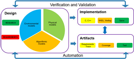
Verification: Phased lockdown

When I release a model it will

  • Reach 100% requirements coverage for the model
  • Reach 90% test coverage of requirements
    • With 100% passing
  • Be in full compliance with 70 Modeling Guidelines
    • Reach 90% compliance with an additional 7
  • Achieve 95% MISRA compliance
    •  100% with exception rationale
  • …

However, if I asked anyone to reach these levels early on in the development process then I would both slow down the process and increase the frustration of the developers.

Image result for I hate my manager

What is a phased approach to verification?

The phased approach to verification imposes increasing levels of verification compliance as the model progresses from the research phase to the final release.releasePhases

The following recommendations are rough guidelines for how the verification rigor is applied at each phase.

Research phase

The research phase has the lowest level of rigor.  The model and data from this phase may or may not be reused in later phases.  The model should meet the functional requirements within a predetermined tolerance.   Modeling guidelines, requirements coverage, and other verification tasks should not be applied at this phase.

Initial phase

With the model in the initial phase, we have the first model that will be developed into the released model. With this in mind, the following verification tasks should be followed

  • Verify the interface against the specification:  The model’s interface should be locked down at the start of development.  This allows the model to be integrated into the system level environment.
  • Compile with model architecture guidelines:  Starting the model development with compliant architecture prevents the need to rearchitect the model later in development.
  • Create links to high-level requirements:  The high-level requirements should be established with the initial model.

Development phase

The development phase is an iterative process.  Because of this, the level of verification compliance will increase as the model is developed.  As would be expected the level of requirements coverage will increase as the implementation of the requirements is done.  The verification of the requirements should directly follow their implementation.

death-spiral

With respect to the increasing compliance with modeling and MISRA compliance; in general, I recommend the following.

  • 50% guideline compliance/MISRA at the start of the development phase
  • 70% guideline compliance/MISRA when 50% of the requirements are implemented
  • 90% guideline compliance/MISRA when 80%  of the requirements are implemented

Release phase

With the release phase, I finally hit the targets I initially described.  Entering this phase from development all of the functional requirements should be complete. The main task of the release phase is the final verification of requirements and compliance with guidelines (model and code).

Additionally, the release phase may include a “targeting” component; where the model which was designed for a generic environment is configured for one or more types of target hardware.  In this case the functionality of the component should be verified for each target.Image result for release

Final thoughts

Ramping up compliance with verification tasks is a standard workflow.  The suggested levels of compliance during the development phase should be adjusted based on a number of factors including

  • Reuse of components:  When components are reused the compliance should be higher from the start of development.
  • Compliance requirements: If you are following a safety critical workflow, such as DO-178C or IEC-61508, then the compliance should be higher from the start of development.
  • Group size:  The more a model is shared among multiple people the sooner the model should be brought into compliance with modeling guidelines.  This facilitates understanding of the model under development


Model-Based Design: The handoff between companies…

Outsourcing design is common in most industries; from simple sub-components to the full system.  In both cases the process by which the handoff between companies happens is critical.

It starts before you start (pre-project work)

Before theImage result for start first model is exchanged, before the first requirement is written the two companies need to agree on  the following items

  1. What materials are delivered
    1. Models, protected models?
    2. Data dictionary?
    3. Test models, test cases?
    4. Generated code?
    5. Requirements?
    6. Interface control document (ICD)?
    7. …
  2. How are the materials delivered?
    1. Using Simulink Projects?
    2. Binaries?
    3. …
  3. What level of model customization is enabled?
    1. Parameter tunning?
    2. variant tuning?
    3. …
  4. How will the requirements be validated?
    1. Requirements tracking through traceability matrix?
    2. Requirements based testing?
    3. …

Regardless of what is specified the information that is required needs to be clearly defined.

Stages of development

An additional factor to consider is the stage of the development.  The materials that are handed over during the initial versus final stages of development will be different.  Normally during the early stages of development, the level of compliance will be lower.  As the development matures the rigor for compliance increases.

Related image

Recommendations for delivery

The following are recommendations for three stages of a “Company-to-Company” project.  The stages I will look at are “Initial specification”, “functional review” and “final delivery”

Image result for package delivery

Initial specification

In the initial specification phase, the Requesting Company (RC) is providing requirements to the Providing Company (PC).  At a minimum, they should provide the following information.

  1. Functional requirement document: A formal document describing how the software should perform
  2. Required level of testing for acceptance: A description of the level, or class, of testing to be performed.  This may include some existing acceptance tests.
  3. Interface control document (ICD):  Description of the software interface, including I/O, rates and tolerances
  4. “Real-world data”:  Any specification sheets for the unit under design and or any existing performance data from the unit

Image result for init

Functional review

In most cases, the functional review stage is an iterative process with the Providing Company providing updates to the Requesting Company.

Related image

At a minimum, the providing company should provide the following artifacts

  1. Simulatable model:  The model could be delivered in a protected mode, keeping the PC intellectual property protected.
  2. Requirements traceability report:  A report on the current status of requirements implementation.  Note: at this stage, the not all of the requirements may have been implemented.
  3. Verification results:  Related to the requirements report the verification results demonstrate the compliance with the requirements.  Note: at this stage, not all of the tests may have been implemented or in a passing stage.
  4. Change requests: During the functional reviews the PC should provide change and clarification requests

Depending on what was decided in the pre-work phase the providing company may provide the test environment and test cases.

In response to these artifacts, the requesting company should provide, at a minimum, the following documents.

  1. Change request response: The requesting company should respond with approval or clarifying information.
  2. Change request: The requesting company should also formally provide any requests to the

Final Deliverable

With the final deliverables, the providing company should provide the same materials as in functional reviews.  The difference is that in the final review requirements traceability and verification results should be completed.  Any requirements that could not be met should have been addressed in the final functional review change request.

handOffFlow

Final thoughts

The process of handing off artifacts between companies in the Model-Based Design environment is nearly identical to that of the traditional text-based environment.  The primary difference is that MBD enables the simulation of the model enabling the requesting company to easily verify the requirements.

Likewise, the specification of which artifacts, and in what format, will be exchanged in the pre-work phase is critical to the success of work between companies.


Things I learned in 2017: MBD edition

With 2017 behind us and 97 blog posts under my belt, it seemed like a good time for some reflection on the state of Model-Based Design.

  1. New industries adopt, old industries expand
    In the past 3 years, the Medical device industry has embraced the core aspects of Model-Based Design feverishly.  At the same time existing strong users, such as Aerospace and Automotive have expanded the tool suite they use to include things such as big data and image processing
    Image result for Cross industry
  2. Growth of continuous integration 
    The use of CI systems for model and system level validation continues to grow.  This is aided by both the growing ease of use for CI systems and…
    Image result for CI images
  3. Improvements in testing infrastructure
    Testing infrastructure, from test managers to test reports continues to mature making it easier for end users to develop reusable, scalable testing environments.  Further, it lowers the bar for developing tests allowing software and systems engineers to both run and create tests.

    Image result for Simulink test
    Simulink Test Manager
  4. Puppies!
    Seriously, of all the desktop backgrounds I have used during presentations this one, of my wife and a photo-bombing dog, was the most liked.

    Epping_Deb_8
    My wife at Epping Forest (not our dog)
  5. Traning
    2017 was a lean year for many customers, and in an effort to save on costs they cut back on training.  As a result, the start of many of my engagements involved basic training.  Fortunately, this is a trend that is already changing.
    Image result for eye of the tiger
  6. Things get real (time)
    2017 featured a large increase in the number of Hardware In the Loop (HIL) projects that I worked on.  This came about due to three things

    • Improvements in the Simulink Real-Time API
    • Lower cost of Hardware In the Loop systems
    • Improved testing support for Hardware in the Loop systems (see item 3)
      Image result for real time SLRT
      Note: I have no idea why, but this image came up in the search for real-time.  I am keeping it


Final thoughts

2017 was a great year for Model-Based Design projects.  I expect an increase in both the number and depth of these projects in 2018.  I look forward to continuing this blog and the eventual conversion to the book.

Automation do’s and don’ts

As an engineer automation is part of my day-to-day work.  From the ‘start.m” function that runs at the start of MATLAB, the excel formulas that smooth pivot tables, or the GIT macro that allows me to merge two branches.  These are automation functions that other people have already created.  Some of these automatons are things so “common” that I forget they were not they are in fact automation.  What then leads me to automate a task?

The 6 questions

Before I automate a process I ask myself the following questions

  1. How often do I perform the task?
    Once a day? Once a week? Once a quarter?
  2. How long does the task take?
    How long does the task take both for my self and the system running the process?
  3. Do others perform this task?
    Do they follow the same process?  Does variance in the process cause problems?  Do you have a way to push the automation out to others?
  4. How many decision points are there in the process?
    Decision points are a measure of the complexity of the process.
  5. Is the process static?
    Is the process still evolving?  If so how often does it change?
  6. Is it already automated?
    Oddly enough if you found it worthwhile to automate someone else may have already done the work.
    autoFreq

When to and not to automate

If the process is already automated, or if the process is changing frequently it is obvious that work should not be put into the automation.  In general, I put look at a threshold in terms of person-hours per week normalized by the number of people working on the project compared to the effort to implement the automation.

If the person-hours per week is low (under 1) or the return on automation duration is high (over 6 months) then I do not consider the automation a worthwhile investment.

Final thoughts

Automation, when done right, saves us time and allows us to perform other more interesting tasks.  However, it is easy to get stuck in “automation for automation sake” development.  I leave you with two humorists take on automation.


Automation
XKCD: Automation


SMBC: Predictions


Model-Based Design and high integrity workflows

First off what qualifies as “High Integrity Software?”  The base “reference” document that I use is the “NIST Special Publication 500-204: High Integrity Software Standards and Guidelines”

2017-06-27_15-49-24.png

Originally written to support the nuclear power industry it provides a valuable insight into what it means to be “safety critical”

criticalDef

In short, the software must function dependably (in a measurable and definable fashion) for critical functions.  Critical functions being defined as having failure modes that could cause serious injury, loss of life or property.

Model-Based Design and safety-critical software

When considering software design using MBD methodologies for safety-critical software everything starts with the requirements and the validation that those requirements are correctly implemented (this is true for all software).   I consider 4 primary factors

  1. Enhanced understanding of requirements
  2. Enhanced traceability
  3. Handoff error reduction
  4. Automated code generation

Enhanced understanding of requirements

Model-Based Design improves the understanding of requirements in 3 ways.  First, in general, models are easier to interpret than code.  Second, models allow you to easily simulate and visualize their behavior simplifying the understanding of the requirements.  Finally, the ability to link requirements to sections of a model and have those requirements show up in test results improves the chance that the requirements will be correctly implemented.  Image result for simulation animation stateflow

Enhanced traceability

Traceability refers to the act of following the implementation, modification, and validation of requirements.  Model-Based Design improves this process since a single model can be used as the design artifact at multiple stages in the development.  Meaning that once the link between the requirement and the model is made it is maintained.

Image result for requirements

Handoff error reduction

The droppedHandOffhandoff of software artifacts between people and roles (e.g. software developer to software integrator to software test engineer) is a well know point for the introduction of errors.  With Model-Based Design, the same model is used at each stage preventing hand-off errors.

Automated code generation

The use of automatically generated code prevents syntactical errors to which people are prone.  Many standards now allow you to claim credit for the use of auto code in the prevention of these errors.

Final thoughts

Developing safety critical systems for any industry requires following common best practices and established guidelines.  Following a Model-Based Design approach helps with the automation and validation of many of these steps while avoiding critical handoff errors.

Getting more out of your test reports

Did I pass or did I fail?  Yes or No?  What more do I need to know?  Putting aside the failure case, where knowing how you failed is important, let’s start by talking about what information you can know and why you would care about it.

Passing information

Image result for passing laneFirst, remember that there are multiple ways in which a test can “pass.”  Just like in school there can be A, B and C passing grades.  The way the grade is determined is, in part, related to the test type.

  • Coverage:  Pass is determined by reaching a given level of coverage.
  • Standards compliance: Passing is determined by being under a given level of errors and not violating any “critical” standards.
  • Baseline: Executing within a given fault tolerance.
  • Performance: Execution of the process under a maximum and average time

File churn

Another metric of interest to the system and testing engineers is the file “churn rate”.  From the testing perspective, there are two types of churn rate.  First how often is the file updated, second how often is the file referenced by updated files.Related image

Files with high “self-churn” are under development and, in general, should have test cases added as the development process matures.  Files with high “reference churn” are, in contrast, generally mature files that are referenced as utilities or as data.  These files should be “fully” locked down with test cases.

Failure is an option

Just like with passing there are multiple types of failures corresponding to the types of “passing.”  The main question is what sort of information do we bring out from the tests?

Image result for failure

  • Cause of failure:  There are 4 primary causes of failure
    • Test did not meet explicit criteria
    • Test failed to run (test harness bug)
    • Dependency failure (supporting files not present or failing their tests)
    • Performance failure

For each type of failure different “rich” information is desired.

Explicit criteria

For the explicit criteria case the cause of failure, as defined by the test, should be provided.  Any relevant plots, error diagnostics (e.g. line of code or block in model), as well as expected results, should be provided.

Failure to run

In a subset of cases, the failure will be in the testing infrastructure.  In this case, the location of the test infrastructure failure should be reported.  To prevent these types of errors when the testing infrastructure is developed test cases for it should be created.

Dependency failure

A dependency failure is a case of the “expected criteria” failure.  E.g. when working with a system of models one or more of the dependent models or bits of data has an error.  Dependency errors can occur in one of two ways.

  1. The dependent model changed and errors were introduced
  2. The interface between the parent and dependent model changed (in the parent) causing errors

If the error is of the first type then the report is the same as in the explicit error case.  For the second case, an interface report should be created detailing the change in the interface.

Infrastructure performance

The final note for this post is a few thoughts on the infrastructure performance.  Over time as additional tests are added to a system the total time to execute tests will increase.  Therefore monitoring both the execution time of individual tests as well as reusable test components is critical.

Image result for infrastructure failure

When profiling the performance of individual test components having “tests for the tests” is important as you want to make sure that when you improve the performance of a test component you do not change its behavior.


A few thoughts on test orginization…

How do you organize your bookshelf at home?  By the author (works well for fiction), by topic (generally good for non-fiction), by size (let’s face it shelf space can be an issue in home libraries.)  Any of these approaches work fine for small libraries, but when the total number of books starts getting large additional information is required to help organize your library.

Image result for library

Metadata and organization

If you have ever used Twitter (disclaimer: I never have) you have experienced metadata in the form of the #ILikeCats or #MyPoliticianIsGreatYoursIsTheSpawnOfSatan.  Metadata is a tag on an object that allows you to augment the information about the object.

Image result for propertiesImage result for metadata

Properties versus metadata

Metadata should not be confused with properties.  Properties are something inherent to the object.  If we extend our book metaphor then we would see

  1. Properties
    • Book title: Nine princes in amber
    • Author: Roger Zelazny
    •  Instance properties
      • Type: softcover
      • Condition: average
  2. Metadata
    • #Genre_Fantasy
    • #Multi_world
    • #Reread

Image result for nine princes in amber

Properties and metadata for tests

Since properties and metadata allow you to organize tests how do I categorize them?  Equally important, what do I not include?

  1. Properties
    • Model name: Name of the unit under test
    • Test harness: Link to the test harness for the unit under test
    • Test name: Short descriptive name
    • Description: Longer descriptive text that summarizes the test
    • Requirement linkages: Links to any requirements covered by the test
    • Data: Input, and expected outputs
  2. Metadata
    • Supported projects:  To support model reuse the tests should tag for which project(s) the test is valid.
    • Supported targets: A list of the targets on which the test is supported.  Such as  SIL, HIL or PIL testing.
    • Test level: An indication of the frequency with which the test is run, e.g. check-in, nightly, weekly, build.  More complex tests that take longer to run should have a higher level.
  3. What not to include
    • Model and data dependencies: These dependencies can be programmatically determined.  Specification of these dependencies will, over time, become out of date.
    • Version history: The version history should be included in the version control software.

Why we care?

In the course of normal development, there is both a local testing step and a global testing step.  At the local level, developers run tests against their updated models.  However, the developers are not expected to know the full scope of the model they are working with; hence the use of metadata and test properties to allow the test environment to fully exercise the model once it is checked in.

testWF_V2

By leveraging the test properties and metadata we can more easily reuse tests.  Absent the metadata tests would need to be duplicated across multiple test suites; duplication which can lead to the introduction of errors in the test environment.


The most challanging control problem: Home heating for multi-floor homes

Hot air rises; cold air settles.  This is a fundamental law of nature and yet most multi-level homes are not set up to handle this challenge (including mine).  Having recently tried a “smart thermostat” and been very disappointed in it’s performance I have started to conceptually design my own home solution.

Trial 1:  Zone alone

My first trial implementation was a simple manual “zone control” system; e.g. in the winter, the top floors are shut off so the heat rises, in summer the bottom is shut off.

hvac5

This approach worked somewhat but since I have a three story house and the thermostat is on the middle floor I always had a temperature gradient that was greater then I liked.

Trial 2: Internet of things (IOT) and active zone control

We are now entering into the thought experiment part of the post.

zoneControl

In the diagram above S1 ~ S3 are simple temperature sensors that would connect over wifi to the master control (hence the IOT part of this project).  The “Master Controller” would have open and close the ducts for each zone and control the Fan and heating and cooling elements.

So far so standard…

What changes this from a standard system into an interesting problem (for me at least) are the optimization constraints that I am putting onto the system

OBJ 1: Minimize the heat differential across the floors
OBJ 2: Minimize the time to achieve target heat
OBJ 3: Minimize energy usage
OBJ 4: Prevent temperature over/undershoot (e.g. don’t let the top floor overheat in winter, don’t let the basement become an ice house in summer)

To meet these objectives I was going to need a plant model; one that would allow me to model

  1. Multiple zones
  2. Heat flow between the zones
  3. Heat input based on damper status
  4. Changing heat flux from the outside of the house (e.g. day/night cycles)

As often is the case I was able to start with a basic model from The MathWorks.

Winters bane: the cold

Let’s start with the winter time problem; heat rises in the house from the lowest floor out through the attic.  Fundamentally the equation can be expressed as

q = -k * Δu

Basic heat flow due to a  temperature differential.

The second set of equations, e.g. the cost function, I expressed in the following fashion

TotalCost = α1 * fobj_1 + α2 * fobj_2 + α3 * fobj_3 + α4 * fobj_4

For example, the first objective function can be written as

fobj_1= abs(T1 – T2) + abs(T2 – T3)

Setting the alpha weights

The cost function uses a set of α coefficients to set the weights for each cost function.  To set the value of those coefficients two things need to be understood

  1. The normalized value of the function:
  2. The “priority” of the objective:

If you told me the priority of the objectives were

α1== 4
α2== 3
α3== 1
α4== 1

That is not enough to set the alpha coefficients.  For example, in the first objective function the max value is roughly 20 degrees while the second objective has a max value of 600 seconds (the last two had values of 45 and 3)  Therefore my weighted objective functions become

α1== 4 * (600/20)
α2== 3 * (600/600)
α3== 1 * (600/45)
α4== 1 *(600/3)

Augmenting the model

The final step in this project, before running the simulations and optimizations, is to augment the model in support of the multiple zones.  Since the duct controllers do not have a position feedback I have only on/off control over each zone.  This was added to the model and the optimizations started.

zones_Augment

The results

I modeled heat loss in each of the zones, with the maximum heat loss in Zone 3, the highest floor. The heat loss on each floor had an impact on the optimal control results the general pattern was same.

zonesActive

After the initial heating (note the basement started out colder) there is a repeated pattern in the vent control.  The basement, due to heat convection activates first; the top floor also activates.  The middle floor, due to the convection from the basement and lower heat loss then the top floor never activates.

Final thoughts

The model I developed for the house is based on many assumptions; the implementation of the control algorithm allows me to have optimal outcomes regardless of the actual heat convection and heat loss properties of my house.  If I am able to implement this in my house I will let you know how the model compared to the actual results.


Continuous integration testing and Model-Based Design

The practice of continuous integration (CI) is well established within traditional C development environments and is at the core of agile workflows.  Model-Based Design processes are able to extend the base level of CI testing through the use of simulation to validate functional behavior.  While this is possible in traditional environments it requires the development of specific test harnesses which the MBD environment provides for “free”

Continuous Integration: Background

There are 5 best practices for CI systems

  1. All source objects must exist in version control: Source objects are used to create derived objects such as C code or test results.  The derived objects do not need to be kept in the repository.
  2. All operations on the objects must be automated: Operations include code generation, running test, collecting code metrics.
  3. Any commitment to the repository should trigger a build and test operation:  The “level” of test can be set for each check-in.  If the impact of the check-in is localized then a subset of the tests should be run.
  4. Results from build and test are easy to interpret: Every build and test operation should generate a report.  Results in that report should be easy to interpret and, in the case of errors, easy to trace back to the root cause of the error (e.g. which file resulted in the failure.)
  5. Minimize build and test execution time: To the extent possible the execution time of the build and test operations should be minimized.

The continuous integration workflow

The continuous integration workflow has two primary paths, an event, and temporal based triggers.  With the temporally-based trigger, the testing environment is run at predetermined intervals, generally nightly and weekly test runs.  With the event-based triggers, the testing environment is “triggered” by the check-in of a model or related data objects.

CI_Rep

Testing levels

To improve the speed of test execution the concept of test “levels” is introduced.  At each level, the pass/fail criteria are assessed and if passed the next level for that model can be run; failure results halts further testing.

Level Info Runs
Level 1 Smoke tests to ensure that the model updates and passes basic modeling guideline checks Check-in, Nightly, Weekly
Level 2 Functional testing against requirements Checkin, Weekly
Level 3 Coverage and functional testing Weekly

Final considerations

There are multiple continuous integration servers such as Jenkins and TeamCity.   Further, there are multiple version control programs that can be combined with the CI servers (such as Git or SVN).

The key consideration is the set up of testing infrastructure “patterns” that enable simple integration with the CI system down the road.  These testing patterns will be covered in a future post.

Managing company-wide rollouts

First a specification, with this post I am addressing the rollout of Model-Based Design in large corporations, e.g. companies with at least 5 divisions using the Model-Based Design methodologies.   Information on rollouts for smaller companies can be found in the post on “group roll out” in the Model-Based Design roadmap.

The discussion of deploying Model-Based Design across a company requires reviewing the working groups and roles as well as how to maintain common tools and methods across the company.

Roles within the company

There are three roles to address:

  1. Model-Based Design Working Group (MBD-WG)
  2. Model-Based Design Tool and Support Group (MBD-TSG)
  3. Model-Based Design Director (MBD-D)

MBD_Director

Model-Based Design Working Group

The MBD-WG is composed of technical and process experts from each division.  In the initial company rollout, their role is to present their divisions best practices for MBD and, as a group, determine what the common best practices will be.  Once the initial process is delivered their role is to

  1. Suggest improvements to the process
  2. Identify issues with common process for their division
  3. Act as point of contact for their division on MBD

download.jpg

Model-Based Design Tools & Support Group

The MBD-TSG role is to

  1. Provide the common infrastructure for Model-Based Design
  2. Provide training on the use of the Model-Based Design infrastructure
  3. Analyse changes to the MBD tool suite for desirable features
    (e.g. review new releases of tools for features that will provide additional or missing functionality)

download.jpg

Model-Based Design Director

The director role is unique to larger corporations.  download.jpgTheir role is to both arbitrate between groups and to set the overall vision of how Model-Based Design will be implemented within the company.  To that end, there are several requirements for the person filling the role, both technical and managerial aspects.

1.) Understanding of traditional software development processes and Model-Based Design processes

The most obvious is an understanding of the fundamentals of traditional software development and Model-Based Design.  In the role of Model-Based Design Director, they will be responsible for articulating the reasons for the transition to MBD.  This leads to the second requirement.

2.) Experience arbitrating between competing objectives

It is common for different divisions to have developed different approaches to Model-Based Design.  The role of MBD-D includes arbitration between the members of the Working Group to help develop the common infrastructure plan.  In order to do this, the director needs to become familiar with the process and requirements of each division.  This leads to the third requirement.

3.) Dedicated time to the Model-Based Design establishment effort

A common failure point in the establishment of a company-wide Model-Based Design process is having the director’s time split between multiple projects.  During the first three to five years of the establishment effort having the director focused on the establishment of the MBD process is critical.  This includes time to visit each division, meeting with the working group, attending conferences on Model-Based Design.

4.) Ability to articulate the Model-Based Design vision

The final role is to provide information to groups both inside and outside of the active divisions.  Changing processes requires consistent commitment and having a person at the “top” who can articulate a vision greatly enhances the chance that the adoption will succeed.

Final thoughts

The rollout across a large organization presents a number of unique challenges that smaller companies do not face.  These challenges derive from the unique methodologies that each division may have developed during their implementation process.  To minimize these issues the sooner a Model-Based Design Director and MBD-WG can be established the more effective the rollout will be.