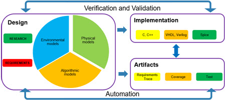
Developing a new product of any kind is an iterative process. The speed of the process is increased using a closed-loop testing methodology.  In a closed loop system, the outputs of the unit under test (UUT) are connected to the plant model. The plant model outputs are, in turn, connect to the inputs of the UUT. Utilizing the ‘closed loop’ setup both the UUT and the plant responds in a “real world” fashion.
The logical question then is
- how do we decompose
- The model’s interface and functions to support closed loop testing
while - Allowing the final model to be deployed to the final target environment
- The model’s interface and functions to support closed loop testing
One model, many paths…
One of the primary objectives of using a Model-Based Design workflow is the ability to use a single model, or group of models, through the full development cycle. Selecting an appropriate top-level architecture simplifies this process.

The model above is a closed loop system with both plant and environmental models. The plant section of the overall model reacts to the feedback from the controller while the parameters from the environmental model are independent of the feedback from the model; such as outside temperature or pressure.
Since the model is intended to run in simulation the hardware inputs and hardware outputs will either be pass through subsystems or signal routing systems. Control over what is in that subsystem accomplished through the use of a variant subsystem. In general, it is a best practice to have a single “target” variant parameter that controls the variants for all of the top-level models.
This decomposition, using variants, allows for the control algorithms to be reused throughout the development process.
The hardware model

In the second example, the model is configured for the deployment to the target hardware. Blocks inside the “Hardware Input” and “Hardware Output” models would include links to the device drivers on the board. Again model variants could be used to reconfigure the hardware input and output subsystems.
As a side note, it is possible to reuse the model in “one model, many paths…” In that case, the Plant and Environment models would be pass throughs set through the variant parameter.
Scaling
Those with sharp eyes will notice that the models are called “hardware input and scaling.” The scaling component converts the digital signals into engineering units. At the high level, the decomposition looks like the following image. On the right (blue) “raw” hardware inputs are read from the sensors. The data is then passed into the green scaling subsystems.

Looking into the analog scaling subsystem we a combination of a simple linear scaling (output = m * input + b) and a Stateflow chart which arbitrates between the redundant signals.
Note, in this case, a design decision was made to place sensor faults in the hardware systems. This was done since the arbitration between the three throttle sensors were being combined into a single throttle position output locally.
Final thoughts
There are multiple approaches to defining the top-level architecture; the key is to define the archtecture early on in the development process to enable integration testing early in the development cycle.

